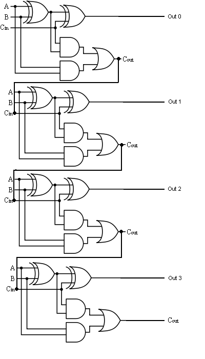
Adder logic projectiot123 introduction binary carry sum outputs Full adder circuit diagram Adder bit logic implementation circuit half adders numbers electronics diagram two carry bits schematic ripple digital add build implement together
logic gates - How to make 2 bit or more half adder circuit - Electrical
Digital logic
The answer is 42!!: four bit full adder tutorial
Full adder logic diagram and truth table : what is a 2-bit full adderDefinition of full adder in digital electronics Adder circuit binary logic output sum xor electronics theorycircuit boolean diagrams derivedFull adder circuit, truth table and verilog code.
Solved problem description: introduction logic circuitsAdder bit circuit half make logic diagram comparator gates first electronics questions cout second there only puzzle connecting solved which Adder truth table circuit verilog codeDigital logic design: full adder circuit.

Full adder
Adder half bit circuit make two logic adders gates combined happened hasSubtractor bit circuit adder logic add control sub line overflow diagram complement detection carry addition zero designing find questions digital Adder circuit logic gates construction electronics ibm binary quantum generator circuits circuitdigestLogic gates.
Logic gatesAdder circuit logic using digital boolean implementation function diagram implement Adder circuit logic diagram javatpoint boolean expression digital actual shownAdder truth logic electronicspost boolean equation input inputs gates implementation.

Half adder logic diagram and truth table / obe assignment: digital
3 bit adder logic circuit designAdder parallel subtractor logic digital bit four truth table addition geeksforgeeks carry working Adder logic gates cout circuits inputs problem xor leetcodeDigital logic.
Adder bit four logic gates byte 4bit nand boolean nor values possible possibilities hold answer trick function known any well .


